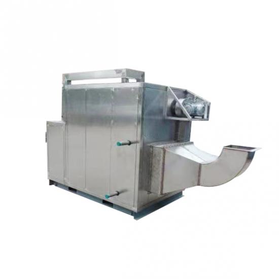
30000m3/H NMP Solvent Recovery System NMP Recycling Machine For Positive Electrode Coating Machine
I.Overview
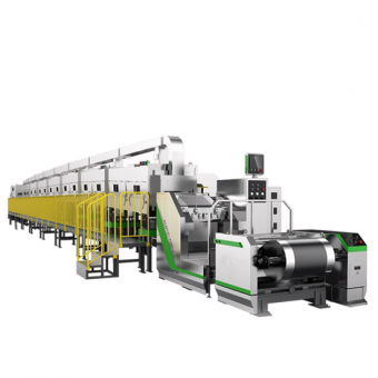
This system equipment is used for one positive electrode single-layer coating machine on the lithium-ion battery production line, with an air volume of 30000 m3/h per unit, and is equipped with one NMP recycling system.
II. Device Description
1. Equipment Introduction
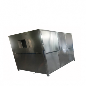
This series of NMP recovery units utilizes the high boiling point (203 ℃) of NMP to condense and freeze 90% to 95% of NMP waste gas for return air while ensuring a dew point temperature of -35 ℃ in the exhaust gas. A small amount of 5-10% waste gas is adsorbed by the runner, reaching a discharge rate of less than 6PPM. This recycling unit has high recycling rate, low operating cost, beautiful appearance, small footprint, superior performance, and easy operation. It can be widely used in the coating process of lithium battery production lines. According to the fact that Party A has one single-layer coating machine with an exhaust air volume of 30000 m3/h, Party B designs two junior high efficiency filter boxes with a processing air volume of 30000 m3/h for Party A, one high-efficiency waste heat recovery unit with a processing air volume of 30000 m3/h, and one NMP condensation refrigeration treatment and recovery unit with a processing air volume of 30000 m3/h.
The equipment is an efficient heat recovery system, with a heat recovery efficiency of up to 75%. It adopts patented technology and a plate exchange structure. Ensure that the return air temperature is around 85 ℃ (when the exhaust air temperature is 110 ℃). Greatly saving heating gas costs and improving efficiency. Reduce the amount of heat emitted into the atmosphere close to room temperature, without generating thermal radiation or heat loss.
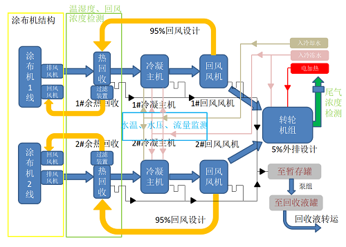
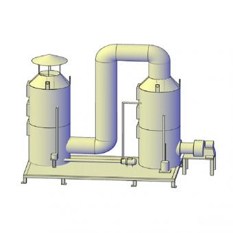
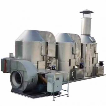
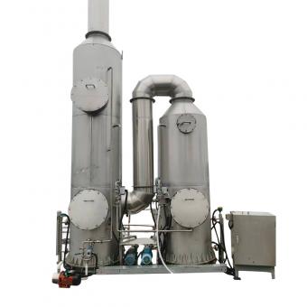
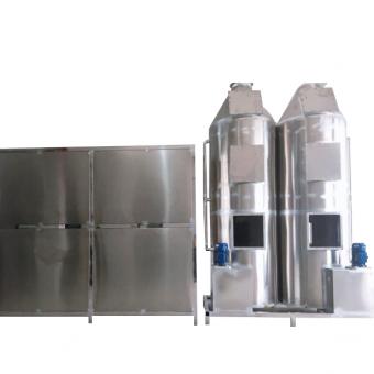
2. Flowchart
Schematic diagram of the process flow of the positive electrode NMP recovery equipment (for reference):
3. System functions
No.
Project
Technical requirement
Notes
1
System startup
The coating machine side can start the recycling system and start in sequence with one click
2
System halt
Delayed shutdown of fan system temperature
3
Automatic control
Automatic detection of NMP recovery concentration
Frequency converter controlled fan; Online detection of NMP concentration detection device
Online detection of NMP concentration/temperature
Set up on-site touch screen and linkage with coating machine
Monitoring of tank level, temperature, and operational status of all motor equipment
4
Monitoring
The outlet and fresh air heating port of the positive gas heat exchanger are equipped with temperature sensors to monitor the temperature of the waste heat recovery device in real time;
5
Alarm
Sound and light color change alarm
6
Run Display
Main parameters run real-time queries
7
Data management
So parameter data can be uploaded to the MES management system
8
Secure
The device has remote and local real-time control and emergency stop, achieving remote adjustment and local control
When designing pipelines, consider slope design, with the direction from the coating machine side to the recycling system from high to low
The system does not backflow, ensuring the normal operation of the coating machine
The system has anti liquid accumulation measures and no residual liquid accumulation
Set one button shutdown button
Positive pole motors, sensors, etc. adopt explosion-proof design
9
Reliable
Shielded pump is designed for online backup and full life cycle design
10
Maintenance free
Maintenance free design
11
Easy to use
According to different permissions, process parameters can be modified online
4、Parameter indicators
1) The parameters of a single positive electrode coating machine provided by Party A
№
entry name
Unit
Specifications
Notes
1
Maximum processing air volume
m3/h
30000
Two in total
2
Temperature of incoming air
℃
120-150
3
NMP concentration of incoming wind
ppm
0~3000
2) Design parameter indicators
No.
Entry name
Unit
Specifications
Notes
1
Emission TVOCS content
ppm
TVOCs≤6
2
Circulating return air volume
m3/h
28500
3
NMP content of circulating return air
ppm
Designed according to 300
4
Circulating return air temperature
℃
≥ 85 (when the incoming air temperature is ≥ 110)
(Positive electrode)
5
Heat recovery efficiency
%
≥ 75 (when the incoming air temperature is ≥ 110)
(Positive electrode)
6
NMP recovery solution concentration
NMP mass fraction ≥ 95
3)Equipment requirements
No.
entry name
Specifications
Notes
1
Equipment safety requirements (special and specific)
Equipment utilization rate ≥ 98%
2
Device speed/CT
NMP recycling capacity
3
Device compatibility
Low humidity recovery without increasing humidity
4
Equipment functional requirements
NMP mass fraction ≥ 95
5
other
Explosion proof function, on-site and remote monitoring function, exhaust temperature, return air temperature, chilled water temperature monitoring function, return air NMP concentration monitoring function
5、List of main equipment configurations
5.1、(List of main configurations for the wheel adsorber of NMP condensation refrigeration recovery equipment)
№
Project
Illustrate
Quantity
Notes
1
Filter box
Model:PJGL-G4-F8-30K
1set
TMAX
2
Waste heat recovery device
Aluminum plate exchange, with an initial effect filter installed at the hot air inlet. PJYRHS-BS-30K
1set
TMAX
3
Condensation host
The main material is SUS304, and the fins are made of aluminum. PJLN-30K
1set
TMAX
4
Exhaust fan
The positive air volume is 30000 m3/h, the air pressure is 2500Pa, the main material of the air passage part is stainless steel, and the explosion-proof level of the motor is ≥ ExdIIBT4
1set
Xinfeng/Guanggu, etc
5
Return air fan
The positive air volume is 28500 m3/h, the air pressure is 2300Pa, the main material of the air passage part is stainless steel, and the explosion-proof level of the motor is ≥ ExdIIBT4
1set
Xinfeng/Guanggu, etc
6
NMP runner unit
Stainless steel material
1set
TMAX
7
NMP adsorption wheel
Material: Super silicone molecular sieve Φ 550 * 400mm
1set
NICHIAS
8
Electric heater
Meet the hot air demand for wheel desorption
1set
TMAX
9
Regeneration fan
The main material of the air passage part is stainless steel, and the explosion-proof level of the motor is ≥ ExdIIBT4
1set
Xinfeng/or equivalent
10
Induced draft fan
The main material of the air passage part is stainless steel, and the explosion-proof level of the motor is ≥ ExdIIBT4
1set
Xinfeng/or equivalent
11
Pressure transmitter
Monitoring exhaust or return air temperature and pressure
3sets
Shanghai Sipai (Positive)
12
Proportional control valve
Chilled water flow rate
1set
Shanghai Sipai
13
PLC
Implement system control
1set
Siemens
14
Touch screen
Implement human-machine interface
2ets
Siemens
15
Inverter
Control the frequency of the fan motor and adjust the air volume
Waste liquid pipeline: SUS304, chilled water pipeline: galvanized seamless steel pipe; Chilled water needs insulation
2sets
Pengjin Guidance
24
Stainless steel ventilation duct
Material 304, fully welded, pressure tested to prevent leakage -3000Pa/two hours without pressure relief. The thickness of the main pipe is 1.0mm. Wrapped with 50MM insulation cotton and wrapped with 0.5mm aluminum skin.
1et
TMAX guides Party A to arrange third-party construction
5.2 control system
1. Equipped with an automatic control system and interlocking system, linked with the coating machine, utilizing exhaust heat and waste heat to send back air to the coating machine, with a return air temperature rise of>75% (heat recovery efficiency); Each set of waste heat recovery system achieves one click start and fully automatic control mode for air outlet; After the coating is completed, the coating machine oven begins to dissipate heat and cool down, and the coating machine exhaust fan is delayed in shutting down. To prevent operators from not shutting down the recycling device in a timely manner, the recycling device is equipped with a temperature control system to detect the temperature of the hot exhaust gas sent out by the exhaust fan of the coating machine. When the temperature of the hot exhaust gas is lower than the set temperature, the recycling device automatically shuts down. It can ensure the safe production and stable operation of the coating machine and recycling device.
2. Set up a monitoring display screen next to the coating machine to monitor the operation status of the recycling system and have an abnormal alarm device. The equipment is equipped with local control, fully considering fan overload, phase loss and leakage protection, and abnormal alarm, making it easy to operate, safe and reliable;
3. The fan adopts a variable frequency speed regulation mode and is used in conjunction with a frequency converter.
After the exhaust gas enters the recovery equipment, temperature alarms are installed at various stages such as the finned heat exchanger, exhaust, and return air to ensure the reliable operation of the equipment.
5. A negative pressure sensor is installed near the coating oven side of the main duct to monitor the internal air pressure of the duct. The variable frequency system is controlled to stabilize the internal air pressure. It can achieve manual and automatic switching functions.
6. The waste heat recovery device adopts patented technology and efficient aluminum plate heat exchanger. The outlet and fresh air heating outlet are each equipped with corrosion-resistant temperature sensors, which are connected to PLC to monitor the temperature of the waste heat recovery device in real-time.
7. Equipped with automatic emission, diagnosis, operation parameter monitoring and alarm functions; Signal line cross-sectional area > 0.5mm
8. The entire NMP and heat recovery unit is equipped with one main control cabinet to control all recovery equipment.
6、Requirements for supporting public works
6.1、Requirements for supporting utilities of NMP recycling equipment (standard condition 22953Nm3/h)
№
Name
Single set usage
Quantity
Specifications
Requirement
1
Cooling water
25T/h
1
32 ℃ cooling water pressure: ≥ 0.3Mpa
The DN65 galvanized steel pipes provided by Party A are respectively connected to the cooling circulating water interface of Party B (condensation host) or provided through air-cooled refrigeration units (including small line NMP removal of cooling capacity)
2
Chilled water
45T/h (36t condensing main unit+9t runner surface cooler with one driven two)
12
7 ℃ chilled water pressure: ≥ 0.3Mpa
The DN80 galvanized steel pipes provided by Party A are respectively connected to the refrigeration circulating water interface of Party B (condensation host) or provided through air-cooled refrigeration units (including small line NMP removal of cooling capacity)
3
Source
80KW (power consumption for the entire system)
1
AC380V/50HZ
The first party needs to connect the primary power supply to the main circuit breaker of the NMP recycling system cabinet
6.2、Process Description:
① The temperature of NMP containing waste gas discharged from a coating machine is about 110 ℃, and it first enters the respective high-efficiency waste heat recovery equipment. After heat exchange, the temperature drops to around 50 ℃; (30000m3/h) enters the respective condensing hosts and further exchanges heat to cool down to below 18 ℃. The NMP concentration in the exhaust gas is less than 300ppm. After the exhaust gas is demisted through the baffle, the treated exhaust gas is heated by efficient waste heat recovery equipment and enters the new air outlet of the respective coating machine. The treated exhaust gas is combined by 5-10% and then introduced into the VOC rotor adsorption section by the rotor induced draft fan for adsorption, reaching a height of up to 6PPM for external discharge.
② The first section of the condensing host is equipped with a cooling water (or refrigeration unit) heat exchanger, where the hot air outside the finned tubes drops below 30 ℃. The second section is equipped with a tube fin type refrigeration heat exchanger, which reduces the exhaust gas to below 18 ℃ through 7 ℃ chilled water. The third section is a mist removal and retention section, which intercepts the majority of NMP droplets.
③ About 20% (300m3/h) of the high concentration exhaust gas generated by the wheel desorption is returned to the surface cooling system in front of the wheel unit for chilled water heat exchange and condensation. 80% (about 2400m3/h) of the low concentration exhaust gas (concentration within 6ppm) is discharged through high-altitude environmental protection.
④ Efficient waste heat recovery involves a small amount of condensed waste liquid, and the vast majority of NMP is condensed from the condensing host and the wheel adsorber. The waste liquid from these three parts naturally flows into the waste liquid buffer tank through gravity.
6.3、Process characteristics
1) Air tightness:
① Stainless steel heat exchanger, pressure test of 25KG to ensure no liquid leakage;
② All condensing hosts are fully welded and subjected to a pressure test of 1MPA;
③ All flange ports shall be processed and tested according to the specifications and standards of the pressure vessel;
④ The filter installed in the air duct and the manually adjusted air valve and other parts with the possibility of air leakage are installed inside the main unit box, and a small door is made outside according to the requirements of the pressure vessel to ensure that no liquid leakage occurs outside the main unit;
⑤ The discharged gas is controlled and regulated by an electric air valve.
2) Energy saving:
① The flow rate of water and the temperature of gas discharge form a closed-loop system to achieve energy conservation;
② The fan adjusts the air volume through a frequency converter;
③ The average total electrical energy consumption of the entire system does not exceed 160KW;
3) Stability:
① When the main fan malfunctions, an alarm will be triggered through the air pressure transmitter and positive pressure sensor;
② When running for a long time, the temperature of the return air is high, and the concentration of the return air cannot reach below 300PPM, the reason is that there is thick dirt on the gas-liquid heat exchange surface; At this point, it is necessary to manually enter the maintenance port for cleaning operations, with an average of twelve internal cleaning operations per year.
3) Guarantee of exhaust emissions:
① The exhaust emissions are absorbed by the wheel and then discharged. Energy saving, maintenance free, and low failure rate. Stable and guaranteed emissions
② There are mature cases to ensure exhaust emissions. The minimum can reach 1PPM.
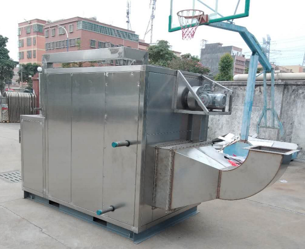
6.4、Recycling system reference diagram
6.5、Supporting air duct (Party A arranges third-party construction)
1) This project adopts SUS304 (stainless steel) rolled plates with a thickness of ≥ 1.2mm,
2) After the production of the air duct is completed, each weld must undergo visual inspection, and each section of the pipeline must undergo a 3000Pa micro pressure leakage test. If there is no leakage within 2 hours, it is considered qualified,
3) Air duct weld treatment: internal pickling and passivation of the pipeline+clean water washing; Externally, steel wire brushes are used to remove welding black spots.
4) Before leaving the factory, the air duct must be knocked on the board wall and then sucked inside with a magnetic strip, and wiped with a clean cloth. After confirming that there are no iron filings, dust, etc., it must be sealed with a special film. It is prohibited to remove it before installation to prevent dust from entering.
6-5-1 Air duct insulation: (Party A arranges third-party construction)
A. Main components: reinforced rock wool insulation cotton, insulation nails, hexagonal mesh, (not limited to this form, the bidder provides a plan, and the bidding party confirms)
B. Surface temperature requirement for air duct insulation layer: ≤ room temperature+5 ° C
C. Insulation material: reinforced rock wool insulation cotton with stainless steel 0.4mm hexagonal mesh outer protection. The insulation material should be rock wool board with a unit weight not less than 100Kg/m3
D. The insulation nails on the outer wall of the air duct should be welded, and special welding equipment should be used for on-site welding to prevent perforation. The distance between them should be W250mm;
Insulation layer construction
E. According to this technical requirement, the insulation construction process for air ducts (main components: reinforced rock wool insulation cotton, insulation nails): if there is a flange welding connection method between the installation sections of the pipeline on site, the flange height is 20-30mm, which is mainly determined by the pipe diameter. The welding of the flange is carried out by manual chlorine arc welding, and the weld seam is full. After welding, the workpiece must be kept flat and not deformed, and the weld seam must be smooth and defect free. The external insulation material of the air duct is made of aluminum foil reinforced rock wool insulation cotton and stainless steel 4mm hexagonal mesh outer protection, insulation material selected is rock wool board with a unit weight of 100Kg/m3 and a thickness of 50mm. (After the installation of the insulation layer, dust, particles, and other pollutants are not allowed to contaminate the oven area)
No.
Project
Technical requirement
Notes
1
Leakage ratio
Equipment leakage rate: V0.5% V0/H
Air duct leakage rate: VO 5% V0/H
Heat exchange leakage rate: V0.5% V0/H
Heat exchange and equipment detection method: leakage rate 0.5% vol/h;
7. Measures for preventing fooling operation
1) User operation interlocking: Users are divided into operating users and administrator users. Operating users can only simply start and stop the equipment and cannot change process parameters. However, administrator users can change process parameters and also operate the start and stop of the equipment to prevent arbitrary changes in process parameters.
2) Device start and stop restrictions: Only logged in operating or administrator users can operate the device to prevent non related personnel from operating the device.
3) Convenience of automatic control: Automatic start can be divided into single machine automatic and online automatic. Single machine automatic means to run independently of the coating machine. In the system, just click on automatic start. Online automatic means to synchronize the start and stop of the coating machine, with a delay. In this state, the recycling system is completely controlled by the coating machine, and users do not need any operation.
4) Convenience of manual control: All manually operated devices are concentrated in the manual operation screen and have detailed noun descriptions, making it easier for users to operate. All devices in the system can be started and stopped separately, and the start and stop conditions are controlled by the program. Users do not need to worry about pressing the wrong button causing equipment damage.
5) System process diagram: A system process diagram will be drawn in the operation screen, indicating the installation location and working status of fans, valves, water pumps, etc. Users can easily monitor the working status of the equipment, and it is easier to understand the equipment based on the process diagram
Operating principle.
6) Parameter settings: The parameter settings are all set to an inputtable range, and users can only modify the parameters within this range. Even if the user accidentally enters an incorrect parameter, the system will automatically correct it within this range, and users do not need to worry about system failures caused by parameter settings errors.
7) Alarm Record: Detailed alarm explanations provide users with the ability to quickly locate system faults. All possible faults in the system have been recorded as alarms, so users do not need to worry about what to do if an alarm occurs.
8) Running status: Green indicates running, while red indicates stopping.
9) Alarm status: Sound, light, and color indication, indicating system faults for the user.
8. Fault and Maintenance (Safety Analysis Form)
№
Fault
Main reasons
Solution measures
1
Power supply phase loss alarm
Phase sequence protector action
Check whether the power supply voltage of each phase is normal and whether the phase sequence protector works normally
2
Leakage alarm
System circuit leakage
Use a megger to check whether the motor is normal, and check whether the lines and cables are damaged.
3
Motor overload alarm
Excessive motor load, current exceeding limit
Check whether the motor bearings are abnormal, stuck, making abnormal noises, whether the pipeline valves are opened correctly, and whether the power voltage is
4
Exhaust overtemperature alarm
The cooling system is not working properly
Within the normal range.
5
Frequency converter fault alarm
Abnormal fan, overload and overcurrent
Check the cooling water circulation system, whether the pipeline valves are correctly opened, whether the circulating pump and water tower Computer fan are normal, and whether the water quality is dirty.
6
Liquid level upper limit alarm of waste liquid tank
Liquid level of waste liquid tank exceeds the limit
Check the liquid level of the waste liquid tank and promptly recover and drain the waste liquid inside the tank.
7
Coating machine linkage does not start
System malfunction or signal abnormality
Check whether the linkage switch button is on the linkage, whether the system has faults that have not been reset, and whether the signal line connecting the coater and the recovery system is normal.
8
The three-phase power supply is normal, but the power indicator is not on
Abnormal control power supply
Check whether the phase sequence protector is normal, whether the control circuit breaker trips, and whether the control fuse is open circuited
9
Air switch frequently trips
Excessive system current exceeding the rated load of the air switch
Check whether the motor current is normal, whether the temperature of the electric box is too high, which causes the thermal tripping of the air switch, and whether the air switch is aging and needs to be replaced.
10
Abnormal vibration and noise of AC contactor
Contactor coil not closing properly
Replace with a new AC contactor.
11
Temperature sensor malfunction
Temperature sensor damaged
Check if the temperature sensor and its circuit are correct
12
Electrical cabinet overtemperature alarm
The temperature of the electrical cabinet exceeds the limit
Check whether the Computer fan is normal and whether the filter screen is dirty and blocked.
13
Unstable recovery rate
The accumulated dust (dirt) on the surface cooler cannot be cleaned after long-term use
When designing, it is important to consider the maintenance port, which can enter the interior of the equipment for easy cleaning and flushing with a high-pressure water gun
14
Equipment leakage
Insufficient welding and pressure testing at the welding site
Except for the maintenance port, all other parts of the equipment must be fully welded and pressure tested, and there must be no liquid leakage
15
The concentration of exhaust emissions does not meet the standard
Clogged or damaged runner
Need to be cleaned or replaced
16
Leakage at flange interface
The flange does not deform and ensures sealing performance
All flange interfaces have too thin thickness, too long spacing, and poor sealing
17
Poor sealing effect
The fan has not undergone pressure testing treatment
The fan needs to undergo pressure testing to a pressure of 5000pa, and the connection of the shaft needs to be sealed with polytetrafluoroethylene as a labyrinth seal
18
Leakage of surface cooler
Poor compression resistance of surface cooler
The surface cooler has a pressure of 3.5MPA and good compression resistance, which will not leak or deform within 5 years
19
Fan selection
Fan air pressure
The selection of fans is crucial. The air pressure should not exceed 20% or too much, as the air flow rate will be too high and affect recycling. The fan should be sealed properly,
20
Equipment leakage
Internal design
In the host, the surface cooler should be elevated by more than 5 centimeters to facilitate the flow of liquid
21
Jumping Qi
Undesigned trap elbow
All liquid pipelines flow downward through gravity and must be equipped with traps
22
Leakage
Poor sealing performance
The soft connection of the fan needs to undergo special process treatment to prevent liquid leakage,
25
Return air concentration not meeting standards
Small design of surface cooler
Appropriate margin should be left in the design based on practical experience
 en
en fr
fr de
de ru
ru es
es pt
pt ko
ko tr
tr pl
pl th
th


 IPv6 network supported


